 Next Generation Virtualization Demands for Critical Infrastructure and Public Services
Introduction
In recent decades communication technologies have realized significant advancement. These technologies now touch almost every part of our lives, sometimes in ways that we do not even realize. As this evolution has and continues to occur, many systems that have previously been treated as discrete are now networked. Examples of these systems are power grids, metro transit systems, water authorities and many other public services.
While this evolution has brought on a very large benefit to both those managing and using the services, there is the rising spectre of security concerns and the precedent of documented attacks on these systems. This has brought about strong concerns about this convergence and what it portends for the future. This paper will begin by discussing these infrastructure environments that while varied have surprisingly common theories of operation and actually use the same set or class of protocols. Next we will take a look at the security issues and some of the reasons of why they exist. We will provide some insight to some of the attacks that have occurred and what impacts they have had. Then we will discuss the traditional methods for mitigation.
Another class of public services is more so focused on the consumer space but also can be used to provide services to ‘critical’ devices. This mix and mash of ‘cloud’ within these areas are causing a rise in concern among security and risk analysts. The problem is that the trend is well under way. It is probably best to start by examining the challenges of a typical metro transit service. Obviously the primary need is to control the trains and subways. These systems need to be isolated or at the very least very secure. The transit authority also needs to provide for fare services, employee communications and of course public internet access for passengers. We will discuss these different needs and the protocols involved in providing for these services. Interestingly we will see some paradigms of reasoning as we do this review and these will in turn reveal many of the underlying causes for vulnerability. We will also see that as these different requirements converge onto common infrastructures conflicts arise that are often resolved by completely separate network infrastructures. This leads to increasing cost and complexity as well as increasing risk of the two systems being linked at some point in way that would be difficult to determine. It is here where the backdoor of vulnerability can occur. Finally, we will look at new and innovative ways to address these challenges and how they can take our infrastructure security to a new level without abandoning the advancement that remote communications has offered. The fact is, sometimes you do NOT want certain systems and/or protocols to ‘see’ one another. Or at the very least there is the need to have very firm control over where and how they can see one another and inter-communicate. So, this is a big subject and it straddles many different facets. Strap yourself in it will be an interesting ride!
Control and Data Acquisition (SCADA)
Most process automation systems are based on a closed loop control theory. A simple example of a closed loop control theory is a gadget I rigged up as a youth. It consisted of a relay that would open when someone opened the door to my room. The drop in voltage would trigger another relay to close causing a mechanical lever to push a button on a camera. As a result I would get a snapshot of anyone coming into my room. It worked fairly well once I worked out the kinks (they were all on the mechanical side by the way). With multiple siblings it came in handy. This is a very simple example of a closed loop control system. The system is actuated by the action of the door (data acquisition) and the end result is the taking of a photograph (control). While this system is arguably very primitive it still demonstrates the concept well and we will see that the paradigm does not really change much as we move from 1970’s adolescent bedroom security to modern metro transit systems.
In the automation and control arena there are a series of defined protocols that are of both standards based and proprietary nature. These protocols are referred to as SCADA, which is short for Supervisory Control and Data Acquisition. Examples of these protocols on the proprietary side are Modbus, BACnet and LonWorks. Industry standard examples are IEC 61131 and 60870-5-101[IEC101]. Using the established simple example of a closed loop control we will take the concept further by looking at a water storage and distribution system. The figure below shows a simple schematic of such a system. It demonstrates the concepts of SCADA effectively. We will then use that basis to extend it further to other uses.

Figure 1. A simple SCADA system for water storage and distribution
The figure above illustrates a closed loop system. Actually, it is comprised of two closed loops that exchange state information between. The central element of the system is the water tank (T). Its level is measured by sensor L1 (which could be as simple as a mechanical float attached to a potentiometer). As long as the level of the tank is at a certain range it will keep the LEVEL trace as ON. This trace is provided to a device called a Programmable Logic Controller (PLC) or Remote Terminal Unit (RTU). In the case of the diagram it is provided to PLC2. As a result PLC2 sends a signal to a valve servo (V1) to keep it in the OPEN state. If the level were to fall below a defined value in the tank then the PLC would turn the valve off. There may be additional ‘blow off’ valves that the PLC might invoke if the level of the tank grew too high. But this would be a precautionary emergency action. In normal working conditions this would be handled by the other closed loop. In that loop there is a flow meter (F1) that provides feedback to PLC1. As long as PLC1 is receiving a positive flow signal from the sensor it will keep the pump (P1) running and hence feeding water into the system. If the rate on F1 falls below a certain value then it is determined that the tank is nearing full and PLC1 will tell the pump to shut down. As an additional precaution there may be an alternate feed from sensor L1 that will only cause a flag to shut down the pump if the tank level reaches full. This is known as a second loop failsafe. As a result, we have a closed loop self monitoring system that in theory should run on its own without any human intervention. Such systems do. But they are usually monitored by Human Management Interfaces (HMI). In many instances these will literally be the schematic of the system with a series of colors (as an example yellow for off, orange & red for warning & alarm, green for running). In this way, an operator has visibility into the ‘state’ of the working system. HMI’s can also offer human control of the system. As an example, an operator might shut off the pump and override the valve close to drain the system for maintenance. So in that example the closed loop would be extended to include a human who could provide an ‘ad hoc’ input to the system.
The utility of these protocols are obvious. They control everything from water supplies to electrical power grid components. They are networked and need to be due to the very large geographic area that they often are required to cover. This is as opposed to my bedroom security system (it was never really intended on security – it was just a kick to get photos of folks who were unaware) which was a ‘discrete’ system. In such a system, the elements are hardwired and physically isolated. It is hard to get into such a room to circumvent the system. One would literally have to climb in the through the window. This offers a good analogy of what SCADA like systems are experiencing. But also one has to realize that discrete systems are very limited. As an example, it would be a big stretch to take a discrete system to manage a municipal water supply. One would argue that it would be so costly as to make no sense. So SCADA systems are a part of our lives. They can bring great benefit but there is still the spectre of security vulnerability.
Security issues with SCADA
Given that SCADA systems are used to control facilities such as oil, power and public transportation, it is important to ensure that they are robust and have the connectivity to the right control systems and staff. In other words they must be networked. Many implementations of SCADA are L2 using only Ethernet as an example for transport. Recently, there are TCP/IP extensions to SCADA that allow for true Internet connectivity. One would think that this is where the initial concerns for security would lie but actually they are just a further addition the systems vulnerabilities. There are a number of reasons for this.
First, there was a general lack in concern for security as many of these environments were at one time fairly discrete. As an example, a PLC is usually used in local control type scenarios. A Remote Terminal Unit does just what it says. It creates a remote PLC that can be controlled over the network. While this extension of geography has obvious benefits, along with it creep the window of unauthorized access.
Second, there was and still is the general belief that SCADA systems are obscure and not well known. Its protocol constructs are not widely published particularly in the proprietary versions. But as is well known, ‘security by obscurity’ is a partial security concept at best and many true security specialists would say it is a flawed premise.
Third, initially these systems had no connectivity to the Internet. But this is changing. Worse yet, it does not have to be the system itself that is exposed. All an attacker needs is access to a system that can access the system. This brings about a much larger problem.
Finally, as these networks are physically secure it was assumed that some form of cyber-security was realized, but as the above reason points out this is a flawed and dangerous assumption.
Given that SCADA systems control some of our most sensitive and critical systems it should be no surprise that there have been several attacks. One example is a SCADA control for sewer flow where a disgruntled ex-employee gained access to the system and reversed certain control rules. The end result was a series of sewage flooding events into local residential and park areas. Initially, it was thought to be a system malfunction, but eventually the hacker’s access was found out and the culprit was eventually nabbed. This can even get into International scales. As critical systems such as power grids become networked the security concern can grow to the level of national security interests.
While these issues are not new, they are now well known. Security by Obscurity is no longer a viable option. Systems isolation is the only real answer to the problem.
The Bonjour Protocol
On the other side of the spectrum we have a service that is often required at public locations that is the antithesis of the prior discussion. This is a protocol that WANTS services visibility. This protocol is known as Bonjour. Created by Apple™, it is an open system protocol that allows for services resolution. Again it is best to give a case point example. Let’s say that you are a student that is at a University and you want to print a document from your iPAD. You can simply hit the print icon and the Bonjour service will send a SRV query for @PRINTER to the Bonjour multicast address of 224.0.0.251. The receiver of the multicast group address is the Bonjour DNS resolution service which will reply to the request with a series of local printer resources for the student to use. To go further, if the student were to look for an off site resource such as a software upgrade or application, the Bonjour service would respond and provide a URL to an Apple download site. The diagram shows a simple Bonjour service exchange.
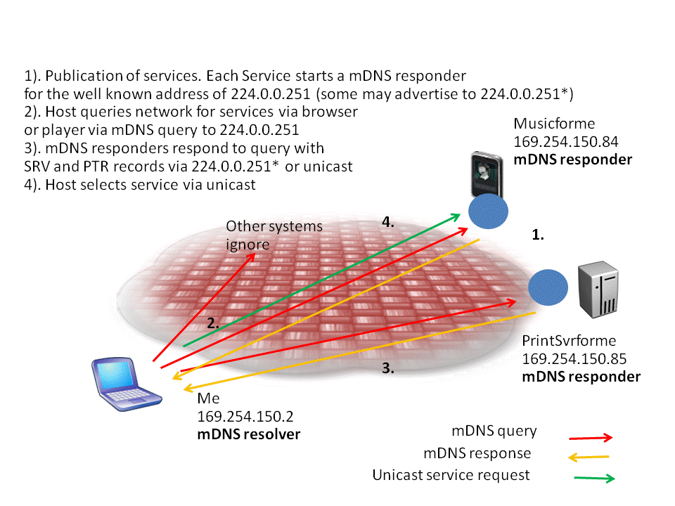
Figure 2. A Bonjour Service Exchange
Bonjour also has a way for services to ‘register’ to Bonjour as well. A good example as shown above is in the case of iMusic. As can see the player system can register to local Bonjour Service as @Musicforme. Now when a user wishes to listen they simply query the Bonjour service for @Musicforme and the system will respond with the URL of the player system. This paradigm has obvious merits in the consumer space. But we need to realize that consumer space is rapidly spilling over into the IT environment. This is the trend that we typically hear of as ‘Bring Your Own Device’ or BYOD. The University example is easy to see but many corporations and public service agencies are dealing with the same pressures. Additionally, some true IT level systems are now implementing the Bonjour protocol as an effective way to advertise services and/or locate and use them. As an example, some video surveillance cameras will use Bonjour service to perform software upgrades or for discovery. Take note that Bonjour really has no conventions for security other than the published SRV. All of this has the security world in a maelstrom. In essence, we have disparate protocols evolving out of completely different environments for totally different purposes coming to nest in a shared environment that can be of a very critical nature. This has the makings for a Dan Brown novel!
Meanwhile, back at the train station…
Let’s now return to our Transit Authority who runs as a part of its services high speed commuter rail service. As a part of this service they offer Business Services such as Internet Access and local business office services such as printing and scanning. They also have a SCADA system to monitor and control the railways. In addition they obviously have a video surveillance system and you guessed it, those cameras use the Bonjour service for software upgrade & discovery. They also have the requirement to run Bonjour for the Business Services as well.
In legacy approaches the organization would need to either implement totally separate networks or a multi-services architecture via the use of Multi-Protocol Label Switching or MPLS. This is an incredibly complex suite of protocols that have very well known CAP/EX and OP/EX requirements and they are high. Running an MPLS network is most probably the most challenging IT financial endeavor that an organization can take on. The figure below illustrates the complexity of the MPLS suite. Note that it also shows a comparison to Shortest Path Bridging IEEE 802.1aq and RFC 6329 as well as the IETF drafts to extend L3 services across the Shortest Path Bridging Fabric.

Figure 3. A comparison between MPLS and SPB
There are two major points to note. First, there is a dramatic consolidation of dependency overlay control planes into a single integrated one provided by IS-IS. Second, as a result to consolidation there results a breaking of the mutual dependence of the service layers into mutually independent service constructs. An underlying benefit is that services are also extremely simple to construct and provision. Another benefit is that these services constructs are correspondingly simpler from an elemental perspective. Rather than requiring a complex and coordinated set of service overlays, SPB/IS-IS provides a single integrated service construct element known as the I-Component Service ID or I-SID.
In previous articles we have discussed how an I-SID is used to emulate end to end L2 service domains as well as true L3 IP VPN environments. Additionally, we covered how I-SID’s can be used dynamically to provide solicited demand services for IP multicast. In this article, we will be focusing on their inherent traits of services separation and control as well as how these traits can be used to enhance a given security practice.
For this particular project we developed the concept of three different network types. Each network type is used to provide for certain protocol instances that require services separation and control. They are listed as follows:
1). Layer 3 Virtual Service Networks
These IP VPN services are used to create a general services network access for general offices and internet access.
2). Local User Subnets (within the L3 VSN)
These are local L2 broadcast domains that provide for normal internet ‘guest’ access for railway passengers. These networks can also support ‘localized’ Bonjour services for the passengers but the service is limited to the station scope and not allowed to be advertised or resolved outside of that local subnet boundary.
3). Layer 2 Virtual Service Networks
These L2 domains are used at a more global level. Due to SPB’s capability to extend L2 service domains across large geographies without the need to support end to end flooding, L2 VSN’s become very useful to support extended L2 protocol environments. Here we are using dedicated L2 VSN’s to support both SCADA and Bonjour protocols. Each protocol will enjoy a private non-IP routed L2 environment that can be placed anywhere within the end to end SPB domain. As such, they can provide global L2 service separated domains simply by not assigning IP addresses to the VLAN’s. IP can still run over the environment as Bonjour requires it, but that IP network will not be visible or reachable within the IS-IS link state database (LSDB) via VRF0.

Figure 4. Different Virtual Service Networks to provide for separation and control.
The figure above illustrates the use of these networks in a symbolic fashion. As can be seen, there are two different L3 VSN’s. The blue L3 VSN is used for internal transit authority employees and services. The red L3 VSN is used for railway passenger internet access. Note that there are two things of signifigance here. First, this is a one way network for these users. They are given a default network gateway to the Internet and that is it. There is no connectivity from this L3 VSN to any other network or system in the environment. Second, each local subnet also allows for local Bonjour services so that users can use their different personal device services without concern that they will go beyond the local station or interfere with any other service at that station.
There are then two L2 VSN’s that are used to provide for inter-station connectivity for the transit authorities use. The green L2 VSN is used to provide for the SCADA protocol environment while the yellow L2 VSN provides for the Bonjour protocol. Note that unlike the other Bonjour L2 service domains for the passengers, this L2 domain can not only be distributed within the stations but between the stations as well. As a result, we have five different types of service domains each one is separated, scoped and controlled over a single network infrastructure. Note that in the case of a passenger at a station who is bringing up their Bonjour client, they will only see other local resources, not any of the video surveillance cameras that also use Bonjour but do so in the totally separate L2 service domain that has absolutely no connectivity to any other network or service. Note also that the station clerk has a totally separate network service environment that gives them confidential access to email, UC and other internal applications that tie back into the central data center resources. In contrast, the passengers at the station are provided Internet access only for general browsing or VPN usage. There is no viable vector for any would be attacker in this network.
Now the transit authority enjoys the ability to deploy these service environments at will any where they are required. Additionally, if requirements for new service domains come up (entry and exit systems for example), they can be easily created and distributed without a major upheaval of the existing networks that have been provisioned.
Seeing and Controlling are two different things…
Sometimes one service can step on another. High bandwidth resource intense services such as multicast based video surveillance can tend to break latency sensitive services such as SCADA. In a different example project, these two applications were in direct conflict. The IP multicast environment was unstable causing loss of camera feeds and recordings in the video surveillance application. The SCADA based traffic light control systems experienced daily outages. In a traditional PIM protocol overlay we require multiple state machines that run in the CPU. Additionally, these state machines are full time meaning that they need to consider each IP packet separately and forward accordingly. For multicast packets there is an additional state machine requirement where there may be various modes of behavior based on whether it is a source or a receiver and whether or not the tree is currently established or extended. These state machines are complex and they must occur for every multicast group being serviced.

Figure 5. Legacy PIM overlay
Each PIM router needs to perform this hop by hop computation, and this needs to be done by the various state machines in a coordinated fashion. In most applications this is acceptable. As an example, for IP television delivery there is a relatively high probability that someone is watching the channels being multicast (if not, they are usually promptly identified and removed. Ratings will determine the most viewed groups). In this model, if there is a change to the group membership, it is minor and at the edge. Minor being the fact that one single IP set top box has changed the channel. The point here is that this is a minor topological change to the PIM tree and might not even impact it at all. Also, the number of sources is relatively small to the community of viewers. (200-500 channels to thousands if not tens of thousands of subscribers)
The problem with video surveillance is that this model reverses many of these assumptions and this causes havoc with PIM. First, the ratio of sources to receivers is reversed. Also, the degree of the ratio changes as well. As an example, in a typical surveillance project of 600 cameras there could be instances as high as 1,200 sources with transient spikes that will go higher during state transitions. Additionally, video surveillance applications typically have the phenomenon of ‘sweeps’, where a given receiver that is currently viewing a large group of cameras (16 to 64) will suddenly change and request another set of groups.
At these points the amount of required state change in PIM can be significant. Further, there may be multiple instances of this occurring at the same time in the PIM domain. These instances could be humans at viewing consoles or they could be DVR type resources that automatically sweep through sets of cameras feeds on a cyclic basis. So as we can see, this can be a very heavy lift application for PIM and tests have validated this. SPB offers a far superior method for delivering IP multicast.
Now let us consider the second application, the use of SCADA to control traffic lights. Often referred to as Intelligent Traffic Systems or ITS. Like all closed loop applications, there is a fail safe instance which is the familiar red and yellow flashing lights that we see occasionally during instances of storms and other impediments to the system. This is to assure that the traffic light will never fail in a state of permanent green or permanent red. As soon as communication times out, the failsafe loop is engaged and maintained until communications is restored.
During normal working hours the traffic light is obviously controlled by some sort of algorithm. In certain high volume intersections this algorithm may be very complex and based on the hour of the day. In most other instances the algorithm is rather dynamic and based on demand. This is accomplished by placing a sensing loop at the intersection. (Older systems were weight based while newer systems are optical.) As a vehicle pulls up to the intersection its presence is registered and a ‘wait set’ period is engaged. This presumably allows enough time for passing traffic to move through the intersection. In instances or rural intersection this wait set period will be ‘fair’. Each direction will have equal wait sets. In urban situations where there are minor roads intersecting with major routes the wait set period will be in strong favor of the major route. With a relatively large wait set period for the minor road. The point in all of this is that these loops are expected to be fairly low latency and there is not expected to be a lot of loss in the transmission channel. Consequently, SCADA tends towards very small packets that expect very fast round trip with minimal or no loss. You can see where I am going here. The two applications do not play well together. They require separation and control.

Figure 6. Separation of IP multicast and Scada traffic by the use of I-SIDs
As was covered in a previous article (circa June 2012) and also shown in the illustration above. SPB uses dynamic build I-SIDs with a value greater than 16M to establish IP multicast distribution trees. Each multicast group uses a discrete and individual I-SID to create a deterministic reverse path forwarding environment. Note also that the SCADA is delivered via a discrete L2 VSN that is not enabled for IP multicast or any IP configuration for that matter. As a result, the SCADA elements are totally separated from any IP multicast or unicast activity. There is no way for any traffic from the global IP route or ip vpn environment to get forwarded into the SCADA L2 VSN. There is simply no IP forwarding path available. The figure above illustrates a logical view of the two services.
The end result of the conversion changed the environment drastically. Since then they have not lost a single camera or had any issues with SCADA control. This is a direct testament to the forwarding plane separation that occurs with SPB. As such both applications can be supported with no issues or concerns that one will ‘step on’ the other. It also enhances security for the SCADA control system. As there is no IP configuration on the L2 VSN (note that IP could still ‘run’ within the L2VSN – as for example as is possible with the SCADA HMI control consoles), there is no viable path for spoofing or launching a DOS attack.
What about IP extensions for SCADA?
As was mentioned earlier in the article there are methods to provide for TCP/IP extension for SCADA. Due to the criticality of the nature of the system however, this is seldom used due to the costs of securing the IP network from threat and risk. As with any normal IP network, protecting them to the required degree is difficult and costly. Particularly since the intention of the protocol overlay is provide for things like mobile and remote access to the system. Doing this with the traditional legacy IP networking with would be a big task.
With SPB, L3 VSN’s could be used to establish a separated IP forwarding environment that can then be then directed to appropriate secure ‘touch points’ within a predefined point in the topology of the network. Typically, this will be a Data Center or a Secured DMZ adjunct from it. There all remote access is facilitated through a well defined security series of Firewalls, IPS/IDS’s and VPN Service points. As it is the only valid ingress into the L3 Virtual Service environment, it is hence much easier and less costly to monitor and mitigate any threats to the system with clear forensics in the aftermath. The illustration below shows this concept. The message is that while SPB is not a security technology in and of itself, it is clearly a very strong compliment to those technologies. If used properly it can provide the first three of the ‘series of gates’ in the layered defense approach. The diagram below shows how this operates.

Figure 7. SPB and the ‘series of gates’ security concept
In a very early article on this blog post I talked to the issues and paradigms of trust and assurance. (See Aspects and characteristics of Trust and its impact on Human Dynamics and E-Commerce – June 2009)
There I introduced the concept of composite identities and the fact that all identities in cyber-space are as such. This basic concept is rather obvious when it speaks to elemental constructs of device/user combinations, but it gets smeared when the concept extends to applications or services. Or it can extend further to elements such as location or systems that a user is logged into. These are all elements of a composite instance of a user and they are contained within a space/time context. As an example, I may allow user ‘A’ for access application ‘A’ from location ‘A’ with device ‘A’. But any other location, device or even time combination may provide a totally different authentication and consequent access approach. This composite approach is very powerful. Particularly when combined with the rather strong path control capabilities of SPB. This combination yields an ability to determine network placement based on user behavior patterns. Those expected and within profile, but more importantly for those that are unusual and out of the normal users profile. These instances require additional challenges and consequent authentications.
As noted in the figure above, the series of gates concept merges well within this construct. The first gate provides identification of a particular user/device combination. From this elemental composite, network access is provided according to a policy. From there the user is limited to the particular paths that provide access to a normal profile. As a user goes to invoke a certain secure application, the network responds with an additional challenge. This may be an additional password or perhaps a certain secure token and biometric signature to reassure identity for the added degree of trust. This is all normal. But in the normal environment the access is provided at the systems level thereby increasing the ‘smear’ of the user’s identity. A critical difference in the approach I am referring to is that the whole network placement profile of the user changes. In other words, in the previous network profile the system that provides the said application is not even available by any viable network path. It is by the renewal of challenge and additional tiers of authentication that such connectivity is granted. Note how I do not say access but connectivity. Certainly systems access controls would remain but by and large they would be the last and final gate. At the user edge, whole logical topology changes occur that place the user into a dark horse IP VPN environment where secure access to the application can be obtained.
Wow! The noise is gone
In this whole model something significant occurs. Users are now in communities of interest where only certain traffic pattern profiles are expected. As a result, zero day alerts of anomaly based IPS/IDS systems become something other than white noise. They become very discrete resources with an expected monitoring profile and any anolamies outside of that profile will flag as a true alert that should be investigated. This enables zero day threat systems to work far more optimally as their theory of operation is to look for patterns outside of the expected behaviors that are normally seen in the network. SPB compliments this by keeping communities strictly separate when required. With a smaller isolated community it is far easier to use such systems accurately. The diagram below illustrates the value of this virtualized Security Perimeter. Note how any end point is logically on the ‘outer’ network connectivity side. Even though I-SID’s traverse a common network footprint they are ‘ships in the night’ in that they never see one another or have the opportunity to inter-communicate except by formal monitored means.

Figure 8. An established ‘virtual’ Security Perimeter
Firewalls are also notoriously complex when they are used for community separation or multi-tenant applications. The reason for this is that all of the separation is dependent on the security policy database (SPD) and how well it covers all given applications and port calls. If a new application is introduced and it needs to be isolated the SPD must be modified to reflect it. If this gets missed or the settings are not correct, the application is not isolated and no longer secure. Again SPB and dark horse networking help in controlling user’s paths and keeping communities separate. Now the firewall is white listed with a black list deny all policy after that. Now as new applications get installed unless they are added to the white list, they will be isolated by default within the community that they reside in. There is far less manipulation of the individual SPD’s and far less risk of an attack surface developing in the security perimeter due to a misssed policy statement.
Time to move…
There is another set of traits that are very attractive about SPB and particularly what we have done with it at Avaya in our Fabric Connect. It is something termed as mutability. In the last article on E-911 evolution we talked to this a little bit. Here I would like to go into it in a little more detail. IP VPN services are nothing new. MPLS has been providing such services for years. Unlike MPLS however, SPB is very dynamic in the way it handles new services or changes to existing services. Where the typical MPLS infrastructure might require hours or even days for the provisioning process, SPB can accomplish the same service in a matter of minutes or even seconds. This is not taking into account that MPLS must also require the manual provisioning of alternate paths. With SPB not only are the service instances intelligently extended across the network by the shortest path, they are also provided all redundancy and resilience by virtue of the SPB fabric. If alternate routes are available they will be used automatically during times of failure. They do not have to be manually provisioned ahead of time. The fabric has the intelligence to reroute by the shortest path automatically. At Avaya, we have tested our fabric to a reliable convergence of 100ms or under with the majority of instances falling into the 50ms level. As such mutability becomes a trait that Avaya alone can truly claim. But in order to establish what that is let’s realize that there are two forms.
1). Services mutability
This was covered to some degree in the previous article but to review the salient points. It really boils down to the fact that a given L3 VSN can be extended anywhere in the SPB network in minutes. The principles pointed out from the previous article illustrate that membership to a given dark horse network can be rather dynamic and can not only be extended but retracted as required. This is something that comes as part and parcel with Avaya’s Fabric Connect. While MPLS based solutions may provide equivalent type services, none are as nimble, quick or accurate in prompt services deployment as Avaya’s Fabric Connect based on IEEE 802.1aq Shortest Path Bridging.
2). Nodal mutability
This is something very interesting and if you ever have the chance with hands on experience, please try it. It is very, very profound. Recall from previous articles, that each node holds a resident ‘link state database’ generated by IS-IS that reflects its knowledge of the fabric from its own relative perspective. This knowledge not only scopes topology but resident provisioned services as well as those of other nodes. This creates a situation of nodal mutability. Nodal mutability is the fact that a technician out at the far edge of the network can accidentally swap the two (or more) uplink ports and the node will still join the network successfully. Alternatively, if a node were already up and running and for some reason port adjacencies needed to change. It could be accommadated very easily with only a small configuration change. (Try it in a lab. It is very cool!) Going further on this logic the illustration below shows that a given provisioned node could unplug from the network and then drive over 100’s of kilometers to another location.

Figure 9. Nodal and Services Mutability
At that location, they could plug the node back into the SPB network and the node will automatically register the node and all provisioned services. If all of these services are dark horse then there will authentication challenges into the various networks that the node provides as users access services. This means in essence that dark horse networks can be extremely dynamic. They can be mobile as well. This is useful in many applications where mobility is desired but the need to re-provision is frowned upon or simply impossible. Use cases such as emergency response, military operations or mobile broadcasting are just a few areas where this technology would be useful. But there are many others and the number will increase as time moves forward. There is no corresponding MPLS service that can provide for both nodal and services mutability. SPB is the only technology that allows for it via IS-IS, and Avaya’s Fabric Connect is the only solution that can provide this for not only L2 but L3 services as well as for IP VPN and multicast.
Some other use cases…
Other areas where dark horse networks are useful are in networks that require full privacy for PCI or HIPPA compliance. L3 Virtual Service Networks are perfect for these types of applications or solution requirements. Figure 8 could easily be an illustration for a PCI compliant environment in which all subsystems are within a totally closed L3 VSN IP VPN environment. The only ingress and egress are through well defined virtual security perimeters that allow for the full monitoring of all allowed traffic. This combination yields an environment that, when properly designed, will easily pass PCI compliancy scanning and analysis. In addition, these networks not only are private – they are invisible to external would be attackers. The attack surface is mitigated to the virtual security parameter only. As such, it is practically non-existent.
In summary
While private IP VPN environments have been around for years they are typically clumsy and difficult to provision. This is particularly true for environments where quick dynamic changes are required. As an example, the typical MPLS IP VPN provisioning instances will require approximately 200 to 250 command lines depending on the vendor and the topology. Interstingly much of this CLI activity is not in provisioning MPLS but in provisioning other supporting protocols such as IGP’s and BGP. Also, consider that all of this is for just the initial service path. Any redundant service paths must then be manually configured. Compare with Avaya’s Fabric Connect which can provide the same service type with as little as a dozen commands. Additionally, there is no requirement to engineer and provision redundant service paths as they are already provided by SPB’s intelligent fabric.
As a result, IP VPN’s can be provisioned in minutes and be very dynamically moved or extended according to requirements. Again, the last article on the evolution of E-911 speaks to how an IP VPN morphs over the duration of a given emergency with different agencies and individuals coming into and out of the IP VPN environment on a fairly dynamic basis based on their identity, role and group associations.
Furthermore, SPB nodes are themselves mutable. Once again, IS-IS provides for this feature. An SPB node can unplug from the network and move to the opposite end of the topology which can be 100’s or even 1000’s of kilometers away. There they can plug back in and IS-IS will communicate the nodal topology information as well as all provisioned services on the node. The SPB network will in turn extend those services out to the node thereby giving complete portability to that node as well as its resident services.
In addition, SPB can provide separation for non IP data environments as well. Protocols such as SCADA can enjoy an isolated non IP environment by the use of L2 VSN’s and further they can be isolated so that there is simply no viable path into the environment for would be hackers.
This combination of privacy, fast mutability of both services and topology lend to what I term as a Dark Horse Network. They are dark, so that they can not be seen or attacked due to the lack of surface for such an endeavor. They are swift in the way they can morph by services extensions and they are extremely mobile, providing for the ability for nodes to make whole scale changes to the topology and still be able to connect to relevant provisioned services without any need to re-configure. Any other IP VPN technology would be very hard pressed to make such claims, if indeed they can make them at all! Avaya’s Fabric Connect based on IEEE 802.1aq sets the foundation for the true private cloud.
Feel free to visit my new You Tube Channel! Learn how to set up and enable Avaya’s Fabric Path Technology in a few short step by step videos.

Leave a comment